Project Implementation Plan
For the Mimir
Near-Infrared Imaging Spectrograph
From a report prepared for: Dr. James Breckinridge, National Science Foundation
Date: October 6, 2000
Professor Dan Clemens
Director
Institute for Astrophysical Research
Boston University
1. Project Overview
The purpose of this document is to provide to the NSF a snapshot of the current plan for implementing the design and development of the Mimir instrument. Acceptance of this plan by Dr. Breckinridge is a condition for award of second year NSF funds for this project.
1.1. Mission of the Mimir Instrument
The Mimir instrument is needed to support ongoing and future near-infrared investigations on the Perkins 1.83 meter telescope by Boston University and Lowell Observatory scientists, staff, and students as well as other outside scientists from the astronomical and planetary science communities. Mimir was conceived as a facility instrument replacement and upgrade of the capabilities formerly supplied by the OSU instrument OSIRIS on the Perkins telescope. Mimir will operate in three fundamental modes: imaging, spectroscopy, and polarimetry. It will cover the near-infrared portion of the InSb detector bandpass from just shortward of 0.9mm to 5mm wavelength.
1.2. Dual Institution Development Plan (Division of Responsibilities)
Mimir is being co-designed and co-developed by Boston University and Lowell Observatory to enhance the instrumentation experience of both institutions. We have divided the responsibilities such that Lowell is lead on the detector, readout electronics, computers, and software areas and Boston University is lead on the optical, mechanical, and cryogenic areas. We plan to perform many of the integration and testing activities together. When completed, Mimir will become a facility instrument for the Perkins telescope and will reside on Anderson Mesa at the Perkins telescope facility.
As Lowell has led the NASA proposals, which have funded the majority of the instrument costs, they retain overall project leadership under Dr. Marc Buie. Boston University is under subcontract to Lowell for the NASA portion of this project, under BU PI Dan Clemens. The NSF support for Mimir is to Boston University, under PI Dan Clemens.
The BU team meets twice weekly to review progress and recommend actions. The BU and Lowell teams communicate via telecon every 3-4 weeks to discuss design decisions and to allocate tasks. Face-to-face meetings of BU and Lowell personnel take place about three times per year.
1.2.1. Instrument Team
Individuals at both institutions working on the design and development of Mimir are identified in the following table:
|
Institution |
Person |
Expertise/Responsibility |
Level
of Effort |
Funding
Source(s) |
|
Lowell
Observatory |
Dr.
Marc Buie |
Project
PI; Systems Engineering; Spectroscopy Modes |
4
months/yr |
NASA |
|
|
Dr.
Edward Dunham |
Optics;
Detector & RO Electronics |
1
months/yr |
NASA |
|
|
Brian
Taylor |
Software |
2
months/yr |
NASA |
|
|
Dr.
John Spencer |
Operations,
filters |
0.5
months/yr |
NASA |
|
Boston
Univ. |
Prof.
Dan Clemens |
BU
PI; Optical Design, Systems Engineering; Imaging Modes |
2
months/yr |
NASA
& NSF |
|
|
Dr.
Eric Tollestrup |
Project
Scientist; Mechanics, cryogenics, systems |
7
months/yr |
NASA
& NSF |
|
|
Mr.
Domenic Sarcia |
Mechanical
Engineer |
10
months/yr |
NASA
& NSF |
|
|
Mr.
Dan Eldredge |
Graduate
Student; mechanisms, sensors, testing |
12
months/yr |
NASA
& NSF |
|
|
Prof.
Ken Janes |
Optics;
mechanics; imaging |
0.5
months/yr |
NASA |
|
|
Prof.
Lynne Deutsch |
Optics;
lab testing |
0.5
months/yr |
NASA |
|
|
Dr.
John Noble (at
Lowell Obs.) |
BU
Operations at Lowell Observatory & Perkins |
2
months/yr |
BU |
|
|
Mr.
Joshua Kamp |
Engineering
Undergraduate; mechanical drawings |
Work/Study
student |
NASA |
|
|
Mr.
Greg Lamioux |
Engineering
Undergraduate; mechanical drawings |
Work/Study
student |
NASA |
Two individuals, both recently hired at BU, have provided enormous depth of experience and added key capability to the Mimir team. These are: (1) Dr. Eric Tollestrup, who was hired away from the CfA to BU in March of 2000, and (2) Mr. Domenic Sarcia, a mechanical engineer with over 20 years of cryogenic design and development, who joined the project in August. Tollestrup was Project Scientist for the IRAC instrument on SIRTF. He also designed and developed STELRCAM for the CfA 48” telescope. STELRCAM also uses an InSb array detector to perform 1-5 mm imaging and spectroscopy, experience directly relevant to Mimir. Sarcia headed his own cryogenics company for 15 years, working with firms and suppliers in the Boston area. He brings enormous depth to our mechanical and thermal design efforts.
1.3. Baseline Instrument Description
Our philosophy regarding Mimir is to design a baseline instrument to meet current needs and which will also permit easy upgrades to support enhanced operation in the future. In particular, we are designing now for a full 10x10 arcmin wide-field capability although we are planning to initially implement a 5x5 arcmin capability. In the following, we describe the expected features of the baseline Mimir instrument, show representative ZEMAX and AUTOCAD drawings of the optical and mechanical designs, followed by a summary of our aspirations for future enhancements.
1.3.1. Low-Resolution Spectroscopy
In spectroscopy mode, the baseline Mimir is designed to provide long and short slit low-R (600) spectra across the 1-5mm band (see Table below). This will be implemented with one grism plus order-sorting filters, perhaps with a cross-dispersing prism for orders 2 and 3. The spectra will be imaged onto the 512x512 format array detector. The slits will be aligned along the instrument “up” direction, only. Slit rotation on the sky will be obtained using the existing instrument rotator on the Perkins telescope. Slit sizes will be matched to good, average, and poor seeing conditions to permit efficient spectroscopy.
|
Mimir Baseline Spectroscopy Design |
||||
|
Grism Order |
<l> [mm] |
ll [mm] |
Dl [mm/2 pixels] |
R |
|
1 |
4.00 |
3.13 – 4.87 |
0.00341 |
587 |
|
2 |
2.00 |
1.56 - 2.44 |
0.00171 |
585 |
|
3 |
1.33 |
1.04 – 1.62 |
0.00114 |
583 |
|
4 |
1.00 |
0.78 – 1.22 |
0.00085 |
588 |
1.3.2. Moderate Field Imaging
In imaging mode, Mimir will provide the widest field commensurate with good sampling of the expected seeing at the Perkins site and for the detector format available. This goal translates into pixel sizes of about 0.6 arcseconds and a 5 x 5 arcminute field of view for a 512x512 detector format. This mode is realized by selection of the f/5 camera unit.
1.3.3. Narrow-Field Imaging
A narrow-field imaging mode will provide smaller pixels and a smaller field of view. This mode will support long wavelength broad-band imaging (in the L and M bands) as well as excellent sampling of the PSF during periods of exceptionally good seeing. The characteristic pixel size for this mode is just under 0.2 arcseconds. This mode is realized by selection of the f/17 camera unit.
1.3.4. Pupil Viewing
Another mode will provide the capability to image the pupil onto the detector array with good spatial resolution. This is needed to align the instrument and telescope and to monitor the telescope optical quality with time. For a pupil size of 25mm, imaging the central 450 pixels of the 512 array is desired. This produces an effective resolution at the primary mirror of better than 4mm, which is adequate to permit aligning the cold Lyot stop to mask the oversized primary mirror of the Perkins telescope.
1.3.5. Detector Format
A 512x512 ALLADIN InSb Detector array (a device with one working quadrant of four in a 1024x1024 chip) has been pledged for permanently loan to the project by the Navy at no cost to the project. This detector has the same physical and electrical configurations as a larger 1024x1024 4-quadrant array, hence an upgrade path to a larger FOV is easily realized.
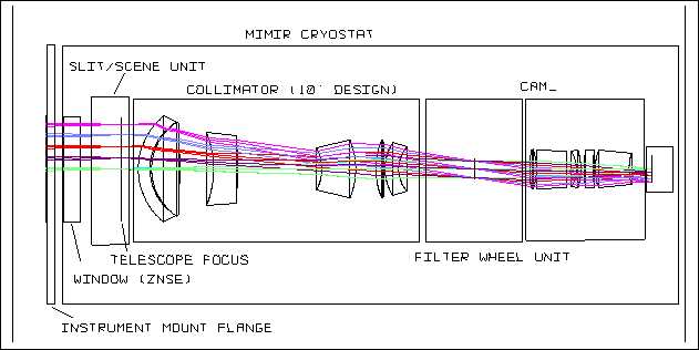
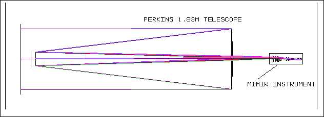
1.4. Optical Designs – ZEMAX
The optical designs are being performed using the ZEMAX design tool. The Concept Design featured separate designs for the Perkins telescope, corrector, collimator, f/5 camera, pupil viewer, and f/17 camera. These designs were integrated into one ZEMAX model during the Preliminary Design phase and are being optimized during the Critical Design phase. The full ZEMAX model , including the Perkins telescope, for the f/5 light path of Mimir is shown in the set of figures below.
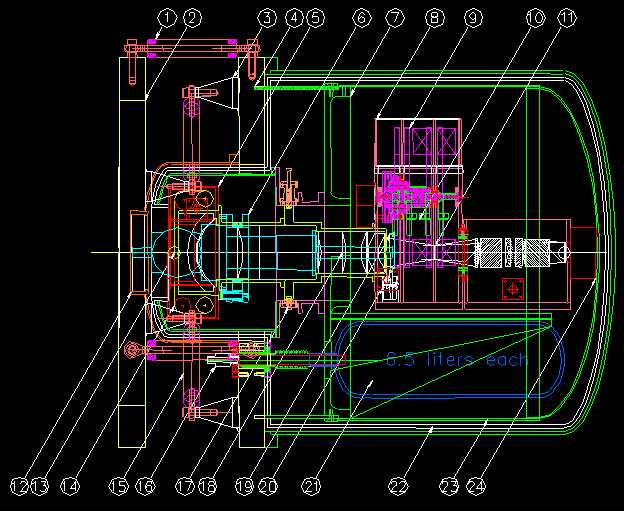
The Mimir mechanical design is being performed by Domenic Sarcia in AUTOCAD 2000. A current drawing is shown below. The overall length from the instrument mounting flange on the left to the bottom of the cryostat shell on the right is just under 40 inches. The overall weight of the fully-loaded instrument will be between 300 and 350 lbs. Many of the mechanical elements of Mimir are labeled in the drawing below: (1) strut in the Z-direction; (2) the telescope mounting flange; (3) strut mount, sitting on the central flange which serves as the vacuum bulkhead for both the upper and lower portions of the cryostat; (4) carbon/epoxy thermal isolating ring; (5) slit unit belt housing; (6) CTI 1050 cryocooler cold head; (7) the internal cold bulkhead, which holds the support bench, the LN2 reservoirs, and the collimator support tube; (8) filter wheel housing cover; (9) filter wheel #2; (10) filter wheel #3 detent; (11) pupil; (12) ZnSe instrument window; (13) location of telescope focus (and slits); (14) slit belt; (15) X, Y struts; (16) LN2 fill tube and relief valve; (17) kinematic support for collimator unit; (18) collimator lens #4; (19) half-wave plates wheel; (20) motor drive for half-wave plate rotation; (21) LN2 storage vessel (one of two); (22) floating thermal shield (1 of 2); (23) active cold shield; (24) InSb array detector housing.
1.6. Instrument Upgrades Descriptions
The baseline Mimir instrument will meet most high priority observing needs already identified by our users. New modes will enable new science, however, and from the beginning of the project several upgrades have been planned. Our philosophy is to explore each of these with enough design detail to enable easy upgrades while deferring the development costs for each mode until funding sources (likely tied to individual science projects) can be identified.
1.6.1. Moderate-Resolution Spectroscopy
A strongly desired upgrade is a medium R (1200-1500) echelle-type mode for the shorter wavelengths, 1-2.4mm. This is needed for planetary atmospheres work as well as for probing star forming regions. This mode requires a high-dispersion grism, likely in concert with a cross-dispersing prism to put multiple orders on the detector array. Implementing this mode is best done with a larger format detector than will be in the baseline instrument.
1.6.2. Wide-Field Imaging
A strongly desired upgrade is to a larger, 10x10 arcminute field of view. This requires a 1024x1024 pixel detector and larger optics for the first three collimator lenses. The ZEMAX drawing shown above carries the optics for the full 10x10 arcmin upgrade.
1.6.3. Polarimetry
Mimir has been designed to support an upgrade to polarimetric capabilities. These capabilities include imaging polarimetry and spectropolarimetry. The units involved in polarimetric analysis are the slit assembly, the first wheel of the four in the filter wheel unit, bandpass filters or grisms in two filter wheels, and Wollaston prism(s) in the final filter wheel. The optical design features no fold mirrors prior to the final filter wheel, which maintains a low instrumental polarization contribution. The slit assembly will be capable of inserting a “picket fence” pattern of 50% fill factor across the 10x10 arcmin field. The baseline design includes a wheel in the filter wheel unit designed to hold six rotating half-wave plates (one each for IJHKLM) to modulate the incoming polarization signal. The Wollaston prism splits the incoming light into two orthogonal polarization senses, which are both imaged onto the detector array. Implementing polarization modes requires upgrading to include the full slit assembly (2 units), half-wave plates in the HWP wheel, motor drive electronics for the HWP wheel, and Wollaston prism(s).
1.6.4. Detector Format
The enhanced Mimir modes require a larger format detector than the 512x512 pixel device to be loaned by the NAVY. Mimir is being designed and fabricated to host InSb arrays of size 1024x1024 pixels. We are seeking Keck Foundation funds this year to support upgrade of the detector to 1024x1024. The Leach readout electronics permit scaling up from 512 to 1024 with a minimum of new boards and little impact on data collection software.
1.7. Predicted Performance
1.7.1. Imaging
In its baseline mode, Mimir’s optics and f/5 camera will provide a 5x5 arcmin field of view with 0.585 arcseconds per pixel across the wavelength range 0.9 to 5mm. Image quality will be seeing-limited or diffraction-limited, but not instrument-limited, from 1-5mm across the entire field of view.
Three filter wheels, each with 10 positions, will contain standard broad-band IJHKLM filters plus additional narrow-band line and off-line filters (user supplied) and order sorting filters for supporting grism spectroscopy.
The initial filter complement is TBD at this time, but will be fixed by the CDR in mid-December.
Optics throughput is estimated at 30%. Detector QE is about 80%. The telescope emissivity is between 10 and 20%. Expected sensitivities are approximately: 20.7 in J; 19.5 in H; 19.1 in K; 14.0 in L; and 11.0 in M. All of these values assume S/N of 3 for one hour of integration on the Perkins telescope. These will become refined as we obtain actual background measurements in the longer wavebands at the Perkins telescope.
1.7.2. Spectroscopic
In its baseline mode, Mimir will have a low-resolution spectroscopic capability based on grisms as the dispersing elements. It will provide R=600 for 1-5mm. Source discrimination will utilize a single slit at the cooled telescope focus. A minimum of three slits will be provided to match to excellent (1.2”), average (1.8”), and poor (2.4”) seeing. Sensitivity is expected to be about the same as for OSIRIS on the Perkins, which was adequate to permit Pluto surface ice monitoring.
1.7.3. Exposure Time Calculator
A Web-based exposure time calculator is being developed and will be featured on a Mimir Web page to be hosted at both Lowell Observatory and Boston University. Lab and telescope data will be used to update this tool.
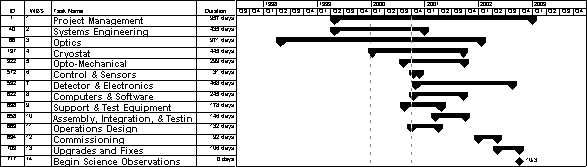
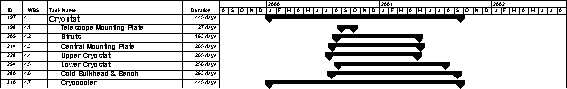
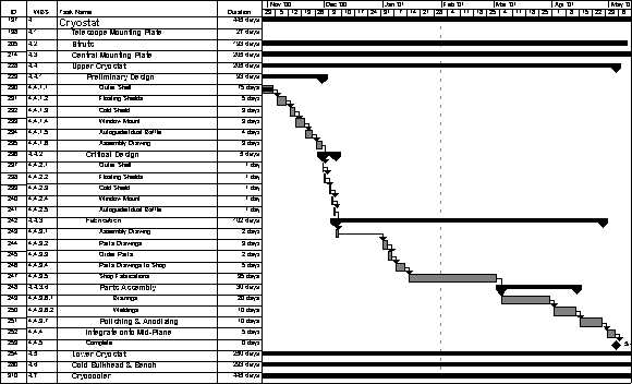
2. Project Schedule
The attached schedule (MS Project form) outlines the phases of the Mimir project and many of the key tasks being performed in each phase. We have completed an eight month Concept Phase, which ended with a Concept Design Review held at Boston University on 16-17 December 1999. We are about to end a ten month Preliminary Design phase and move into an eleven-week Critical Design phase. This will end with a Critical Design Review in early December of 2000, to be held at Boston University. Pending a positive outcome of the CDR, we next proceed to a six month development period of procurements and fabrications. This is followed by eight months of assembly, integration, and testing at both Boston University and Lowell Observatory. We plan to ship Mimir to Lowell on or about 1 November 2001 and to begin commissioning observations on the Perkins telescope around 29 January 2002. This commissioning phase is expected to last for about four months.
We are holding open the option to return Mimir to Boston for a final set of upgrades and repairs/tweaks for the summer of 2002. If Keck Foundation funding has been obtained, we will install the detector and other upgrades at this time. We would plan to ship Mimir one final time back to Lowell in time to begin routine service as the first facility instrument for the Perkins in early October of 2002.